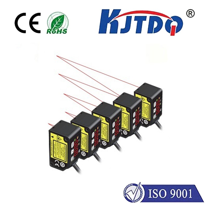
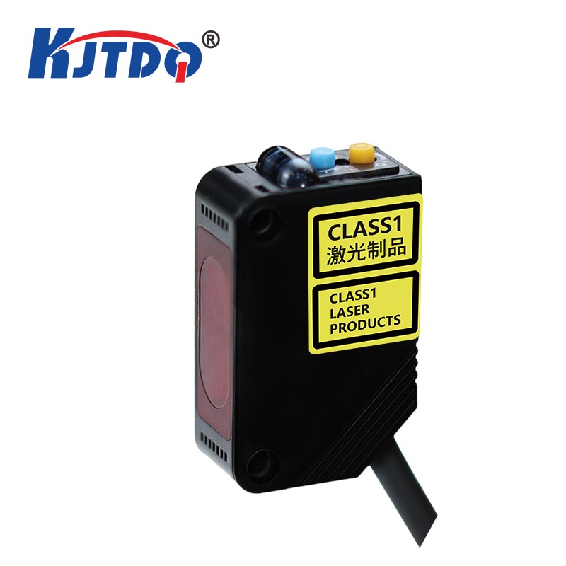
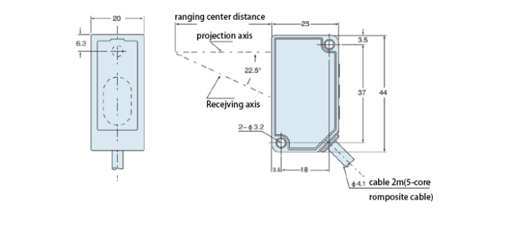
KJT-KELR-TE series laser displacement sensors adopt the triangulation measurement principle and use linear array CMOS devices as optical receiving devices. They have the characteristics of high measurement accuracy and short measurement time. The product optical path has been uniquely designed and the imaging quality is stable. ;With unique fill light technology
![]()
| Supply voltage | Uv12V DC~24V DC±10% | |
| residual ripple | Pulsation P-P10% | |
| Current consumption | 60mA or less (when the power supply voltage is 12VDC) | ≤40mA or less (when the power supply voltage is 24V DC) |
| linearity | ±0.1%F.S | ±0.2%F.S |
| Shell material | Cast aluminum alloy (AL) | Organic glass (PMMA) |
| Connection Type | lead | |
| monitor | 4-digit digital tube | 2xLED |
| Enclosure rating | IP67 | |
| Protection level | III | |
(Note) The measurement conditions when not specified are as follows:
voltage: 24V DC、
Ambient temperature: +20℃、
Response time: 10ms, analog output value of measurement center distance.
Target object: white ceramic. (Note 2): Based on the provisions of Laser Notice No. 50 of FDA regulations and based on FDA.
This value is measured at the center distance. Define these values in terms of 1/e2 (approximately 13.5%) of the central light intensity. If there is light leakage outside the defined area and there are strong reflections around the detection point that are higher than the detection point itself, the detection results may be affected.
| performance | TE40 |
| Measure center distance | 400mm |
| Measuring range | ±200mm |
| Beam diameter | 约φ500μm |
| Repeat accuracy |
300μm (measuring distance 200mm~400mm) 800μm (measuring distance 400mm~600mm) |
| light receiving element | CMOS image sensor | |
| light source | Red semiconductor laser Class 2 (JIS/IEC/GB), Class II (FDA) (Note 2) | |
| control output |
〈NPN output type〉 NPN open collector transistor Maximum inflow current: 50mA Applied voltage: 30VDC or less (between control output and 0V) Residual voltage: 1.5V or less (when the current flowing in is 50mA) Leakage current: 0.1mA or less |
〈PNP output type〉 PNP open collector transistor Maximum source current: 50mA Applied voltage: 30V DC or less (between control output and +V) Residual voltage: 1.5V or less (when the current flowing in is 50mA) Leakage current: 0.1mA or less |
| Analog output | Analog output·Output range: 0V ~ 5V (normal); 5.2V (alarm) Output impedance: 100Ω | |
| Output range: 4mA~20mA (normal); 0mA (alarm) | ||
| action output | Load impedance: 300Ω max; ON when light enters/ON when no light enters can be switched | |
| Short circuit protection | Automatic reset | |
Instructions for use:
The user interaction interface of this product mainly consists of digital tubes, LED indicators and buttons. Digital tubes and LED indicators are used to display product information, and buttons are used to modify product parameters.
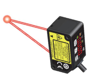
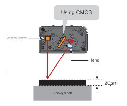
High-precision CMOS image sensor & equipped with algorithm:
Using the high-precision CMOS image sensor used in displacement sensors and our company's unique algorithm that has been used in displacement sensors, we have achieved the high accuracy of 1mm/100mm in micro laser sensors.
Notice:
Do not use this product as a detection device to protect personal safety.
For detection devices designed to protect the human body, please use products that comply with OSHA, ANSI, IEC and other countries' laws and standards on human protective equipment.
Do not operate according to methods not described in the instructions for use that come with the product. If you perform controls or adjustments other than those specified, you may be exposed to dangerous radioactive laser light.
This product is a Class 2 laser product that complies with JIS/IEC/GB standards or a Class II laser product that meets FDA regulations. This product has certain dangers. Please do not look directly at the laser or observe it through a lens, etc.
![]()
![]()
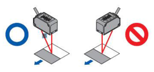
relative to the direction of the moving body
<In case of material and color difference>
When measuring, when the moving measurement objects have extremely different materials and colors, install them in the direction shown in the figure below to minimize the measurement error.
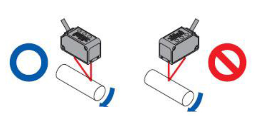
<Detect rotating objects>
When measuring a rotating object, install it in the direction shown in the figure below to suppress the effects of vertical vibration and positional deviation of the object.
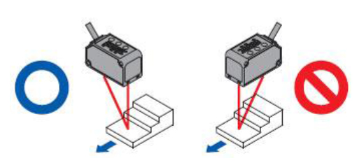
<When there is a step difference>
If there is a step in the moving detection target, install it as follows to suppress the influence of the edge of the step during measurement.
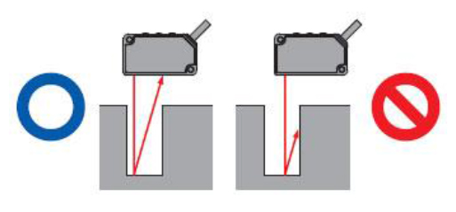
Measure in tight places and recessed parts.
When measuring in a narrow place or hole, be careful not to block the light path from the emitter to the receiver when installing.
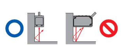
When mounted on the wall
Please install according to the following methods to prevent multiple reflections from the wall from entering the light-receiving part. In addition, if the reflectivity of the wall is high, the effect will be better if it is changed to matte black.
![]()
 Nanjing KJT Electric Co,.LTD

